
Views: 222 Author: Tina Publish Time: 2025-05-17 Origin: Site


Content Menu
● Understanding the LCD 20x4 Display and Its I2C Address
>> What is a 20x4 LCD Display?
>> Default I2C Addresses for LCD 20x4
>> How to Find Your LCD 20x4 I2C Address
● Pinouts and Wiring of LCD 20x4 with I2C Interface
● Programming the LCD 20x4 with I2C Address
>> Initializing the LCD with the Correct Address
>> Displaying Text and Cursor Control
● LCD 20x4 Display Memory Addressing
● Adjusting Contrast and Backlight
● Advanced Tips and Applications
>> Using Multiple LCDs on One I2C Bus
>> Scrolling Text and Animation
● Troubleshooting Common Issues
>> Garbled or Incorrect Characters
● Frequently Asked Questions (FAQ)
>> 1. What is the default I2C address for a 20x4 LCD display?
>> 2. How can I find the I2C address of my LCD 20x4 module?
>> 3. Can I connect multiple 20x4 LCDs on the same I2C bus?
>> 4. How do I adjust the contrast on a 20x4 LCD with I2C?
>> 5. What library should I use to control a 20x4 I2C LCD with Arduino?
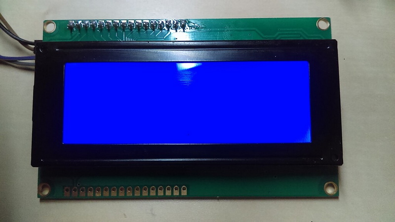
The 20x4 LCD display is a popular alphanumeric module widely used in embedded systems, microcontroller projects, and Arduino applications. It offers 20 characters per line over 4 lines, making it ideal for displaying detailed information in a compact format. One of the most common ways to interface this display is via the I2C communication protocol, which simplifies wiring and conserves microcontroller pins. This article provides an in-depth exploration of the LCD 20x4 display, focusing on the critical question: what address should be used for the LCD 20x4 display when connected via I2C? We also cover pinouts, wiring, programming examples, troubleshooting, and advanced tips to help you get the most out of your display.
A 20x4 LCD display module consists of 4 lines, each capable of showing 20 characters. It typically uses the HD44780 controller or compatible ICs such as ST7066, which manage the display operations. The display can be interfaced in parallel mode or via I2C using an I2C backpack module based on the PCF8574 chip.
The HD44780 controller is a well-established standard for character LCDs. It controls the display by managing the DDRAM (Display Data RAM), CGRAM (Character Generator RAM), and the LCD's internal timing. This controller supports both 4-bit and 8-bit parallel communication modes, but the I2C interface converts the parallel signals into serial communication, reducing the number of pins required.
When using an I2C interface, the LCD module communicates over the I2C bus, which requires a unique device address. The most common default I2C addresses for 20x4 LCD modules are:
- 0x27 (hexadecimal) - the most frequent default address for many I2C LCD modules.
- 0x3F - another common default address depending on the manufacturer.
These addresses correspond to the PCF8574 I/O expander chip integrated into the I2C backpack. The chip's address is determined by the hardware configuration of the address pins (A0, A1, A2). By default, many modules come with all address pins grounded, resulting in the 0x27 address.
Some modules allow address modification by soldering jumpers or pads on the I2C backpack, enabling up to 8 different addresses by setting the A0, A1, and A2 bits. This feature allows multiple LCDs on the same I2C bus without address conflicts. For example, setting A0 high changes the address from 0x27 to 0x26, and so forth.
If your LCD does not respond at the default addresses, you can scan the I2C bus to find the correct address using an I2C scanner. This is a simple program that probes all possible addresses (from 0x03 to 0x77) and reports the addresses where devices respond.
Running an I2C scanner is essential when you have multiple I2C devices or an unknown module. It helps prevent address conflicts and ensures your microcontroller communicates with the correct device.
The I2C LCD module has only four pins:
- VCC: Power supply, usually +5V.
- GND: Ground.
- SDA: Serial Data line for I2C communication.
- SCL: Serial Clock line for I2C communication.
This minimal pin count simplifies wiring compared to traditional parallel LCDs, which require at least 6 pins. The I2C bus also supports multiple devices on the same two wires, making it ideal for complex projects.
To connect a 20x4 I2C LCD to an Arduino Uno:
- Connect VCC on LCD to Arduino 5V.
- Connect GND on LCD to Arduino GND.
- Connect SDA on LCD to Arduino SDA pin (A4 on Uno).
- Connect SCL on LCD to Arduino SCL pin (A5 on Uno).
This wiring scheme is consistent across many Arduino boards, but some boards like the Mega or Leonardo have different SDA and SCL pins. Always refer to your board's pinout diagram.
The LCD module typically operates at 5V, but some newer modules support 3.3V logic. Supplying the correct voltage is crucial to avoid damage. The I2C backpack's PCF8574 chip usually tolerates 5V power and logic levels, but verify the datasheet for your specific module.

To control the LCD 20x4 via I2C, you need the LiquidCrystal_I2C library in the Arduino IDE. This library simplifies communication and provides functions to display text, control backlight, and set cursor position.
The library abstracts the low-level I2C communication and HD44780 commands, allowing you to focus on your application logic.
When creating an instance of the LCD object, you must specify the I2C address and the display size:
cpp:
LiquidCrystal_I2C lcd(0x27, 20, 4);
If your LCD does not respond, try changing the address to 0x3F or run an I2C scanner to find the correct address.
The library provides easy-to-use functions such as:
- `lcd.print("Text")` to display strings.
- `lcd.setCursor(column, row)` to position the cursor.
- `lcd.clear()` to clear the display.
- `lcd.backlight()` and `lcd.noBacklight()` to control the backlight.
Using these functions, you can create dynamic displays, menus, and status indicators.
The LCD controller uses DDRAM (Display Data RAM) addresses to map characters on the screen. For a 20x4 display, the DDRAM addresses for each line are:
| Line | DDRAM Start Address (Hex) |
|---|---|
| 1 | 0x00 |
| 2 | 0x40 |
| 3 | 0x14 |
| 4 | 0x54 |
These addresses are important when you want to set the cursor position precisely or create custom display effects. For example, if you want to write directly to the third line, you would set the DDRAM address to 0x14.
Understanding these addresses is also useful when creating custom characters or scrolling text, as it allows you to manipulate the display memory directly.
Most 20x4 LCD modules have a small potentiometer on the back to adjust the contrast. Turning it changes the visibility of characters. If the contrast is too low, the characters will appear faint or invisible; if too high, the screen may appear black.
For I2C modules without a physical potentiometer, some libraries provide software functions to adjust contrast by sending specific commands to the LCD controller. However, this feature is less common and depends on the module design.
Backlight can often be controlled via a jumper or programmatically through the library's backlight control functions. Turning off the backlight saves power but reduces readability in low-light conditions.
If your project requires multiple LCD displays, you can connect them all to the same I2C bus as long as each has a unique address. This is achieved by setting the address pins (A0, A1, A2) differently on each I2C backpack.
This capability is especially useful in complex embedded systems or dashboards where multiple data sources need to be displayed simultaneously.
The HD44780 controller supports up to 8 custom characters, which you can define by specifying pixel patterns. This is useful for creating icons, symbols, or special alphabets.
The LiquidCrystal_I2C library provides functions to create and display these custom characters, enhancing the visual appeal of your interface.
With 20 characters per line, long messages may not fit on the screen. You can implement scrolling text by shifting the display left or right using LCD commands.
Animations, such as progress bars or blinking indicators, can also be created by updating the display rapidly, providing a dynamic user experience.
- Verify power and ground connections.
- Check the I2C address; run an I2C scanner if unsure.
- Adjust the contrast potentiometer.
- Ensure the correct library is installed and initialized.
- Confirm that the SDA and SCL lines are connected to the correct pins.
- Confirm wiring is correct.
- Make sure the LCD is properly initialized in code.
- Avoid overwriting characters by managing cursor positions carefully.
- Check for electrical noise or loose connections.
- Check jumper settings for backlight control.
- Confirm power supply voltage is correct (usually 5V).
- Some modules have separate pins for backlight; ensure these are connected.
- Use pull-up resistors (typically 4.7kΩ) on SDA and SCL lines if not already present.
- Check cable length and quality; I2C is sensitive to long wires.
- Verify no address conflicts with other I2C devices.
The 20x4 LCD display is a versatile and widely used component for displaying textual information in embedded projects. When interfaced via I2C, it simplifies wiring and conserves microcontroller pins. The default I2C addresses are typically 0x27 or 0x3F, but users should verify their specific module's address with an I2C scanner if necessary. Proper wiring, library installation, and initialization are critical for successful operation. Adjusting the contrast and backlight ensures optimal readability. Advanced features such as multiple LCDs on one bus, custom characters, and scrolling text allow for rich user interfaces. With this knowledge, you can confidently integrate and troubleshoot a 20x4 LCD display in your projects, enhancing your device's interactivity and usability.

The default I2C address is usually 0x27 or 0x3F, depending on the manufacturer and module configuration.
You can use an I2C scanner sketch on your Arduino to detect the address by scanning all possible addresses on the I2C bus.
Yes, if each LCD has a unique I2C address set via jumpers or solder pads, you can connect up to 8 devices on the same bus.
Most modules have a small potentiometer on the back to adjust contrast. For some I2C modules without a potentiometer, software functions may control contrast.
The LiquidCrystal_I2C library is widely used and supports 20x4 LCDs with I2C interface.


